How I Made a Robotic T-Shirt Cannon
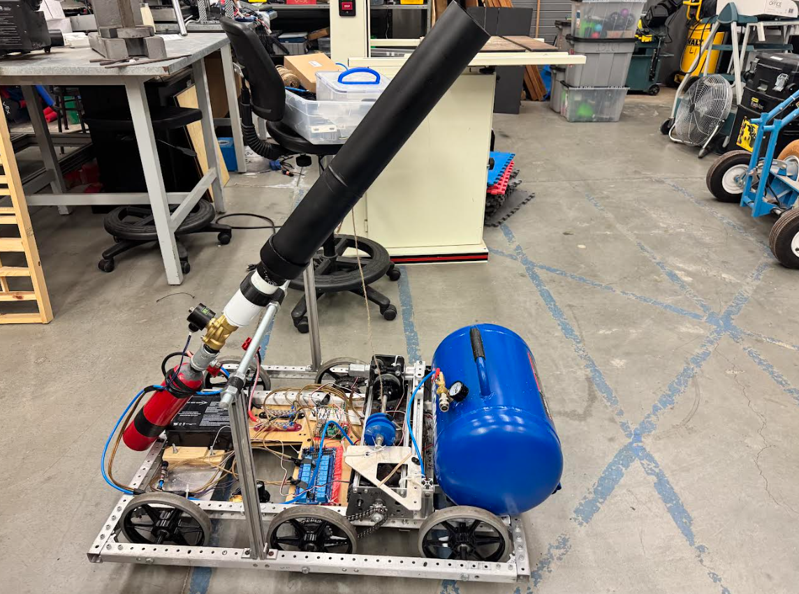
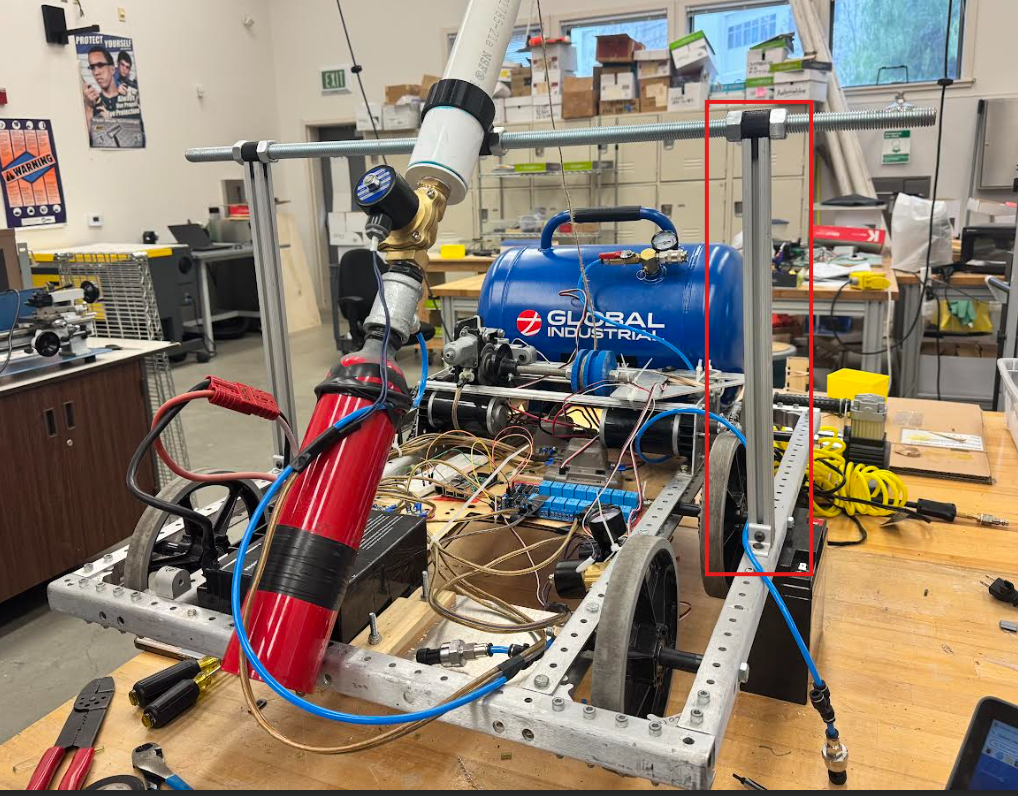
So, I made a robotic t-shirt cannon (image below), and here is how I did it.
One day, while the Robotics club was having a meeting, we came across some old photos.
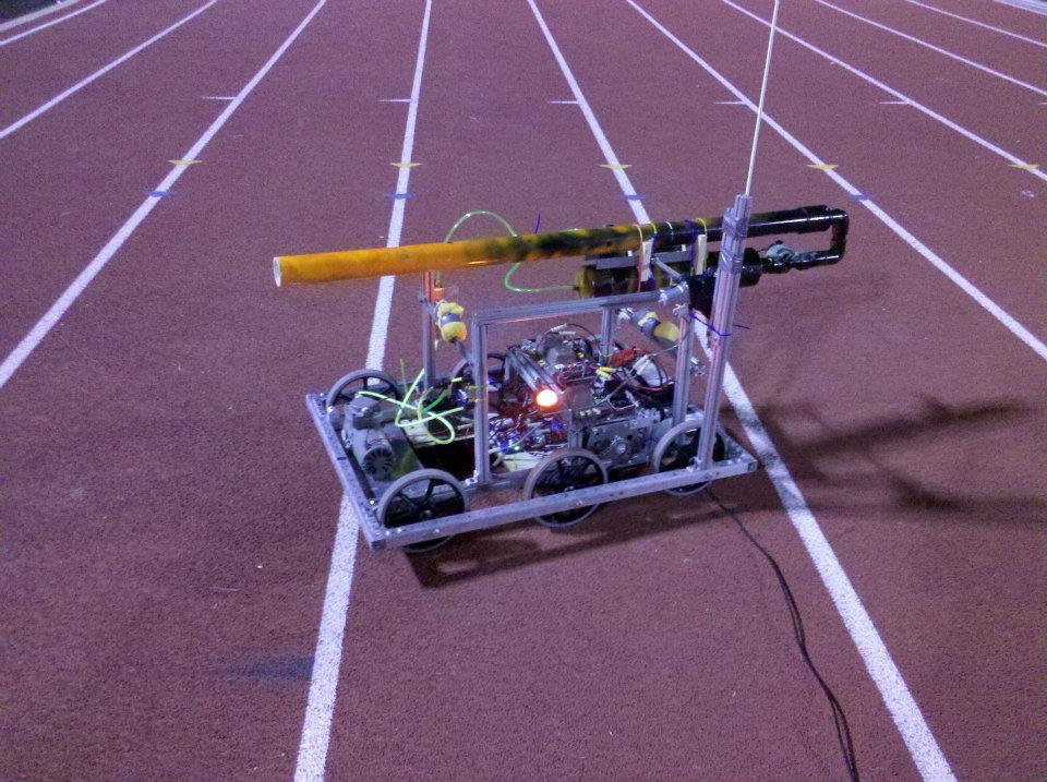
October 2011
We almost immediately identified this contraption as a t-shirt cannon of sorts, although from a quick glance, perhaps the safety prospects weren't the greatest. While we all had a quick laugh over the dubious build quality of this contraption (that was more than a decade old), I figured I could likely revive this project with some heavy changes.
T-shirt cannons are perhaps a staple of many rallies and events, the idea of T-Shirts flying into the audience is a perfect mix of absurdity and interesting. After talking to the school's leadership class, they decided to fully fund the project on the condition that I showcase it at once of their rallies in mid-March. At the time of this conversation, it was right after winter break. To get this done, work had to start at breakneck pace.
I decided that this contraption should be able to do the following
- Launch t-shirts at least 100 feet
- Should be able to shoot at least 30 t-shirts without needing to be recharged (except for inserting the t-shirts)
- Operate remotely without cables, on a robotic base, and be able to do so both indoors and outdoors
- Have an adjustable angle of launch to target various locations without moving
- Be reasonably cheap (~$600)
Old Parts & Drivebase
As I started brainstorming designs for the cannon, I decided to first look into what parts we already have in the school's engineering lab. Much to my surprise, we actually had parts of the old t-shirt cannon.
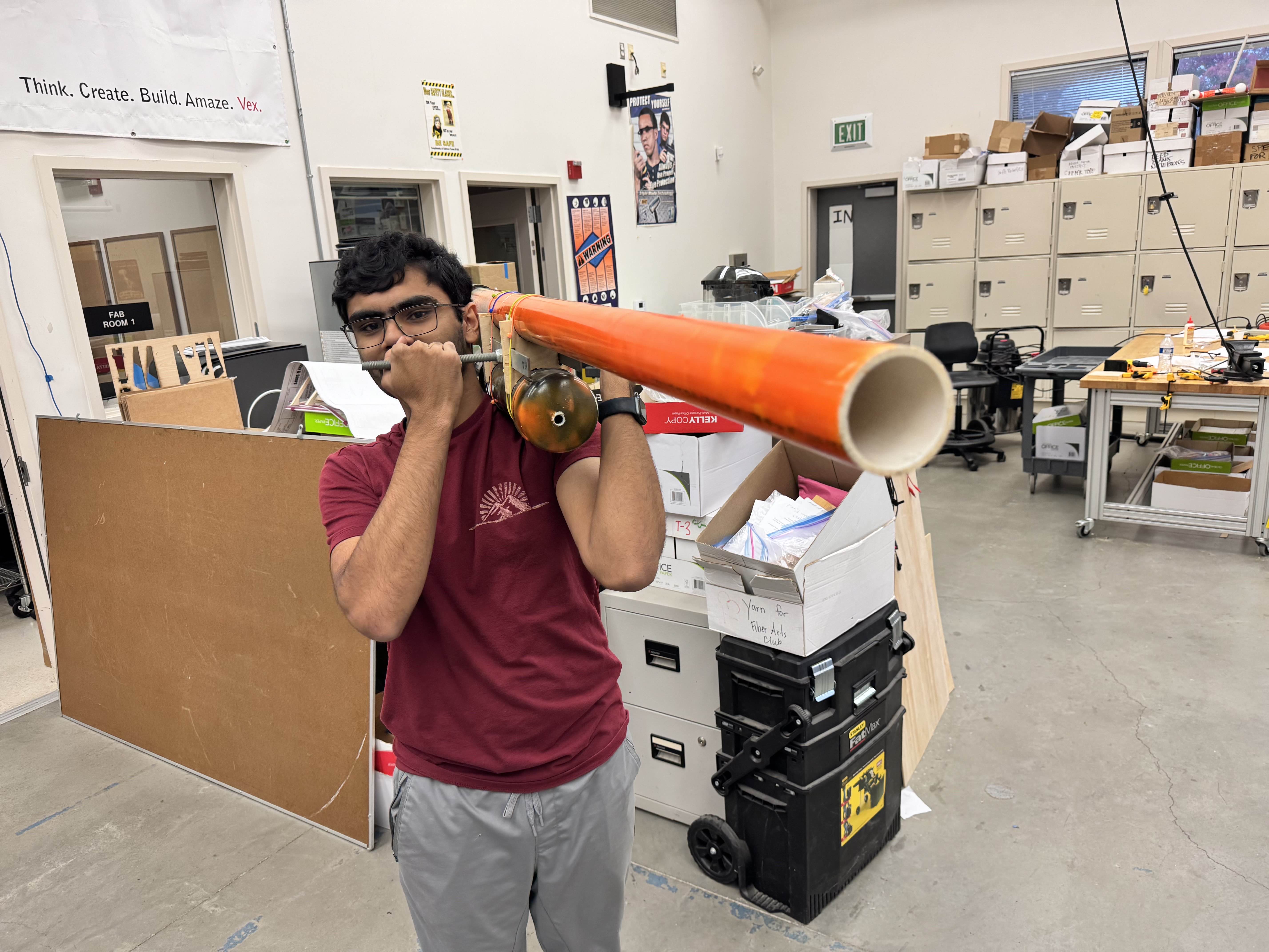 Holding the old cannon
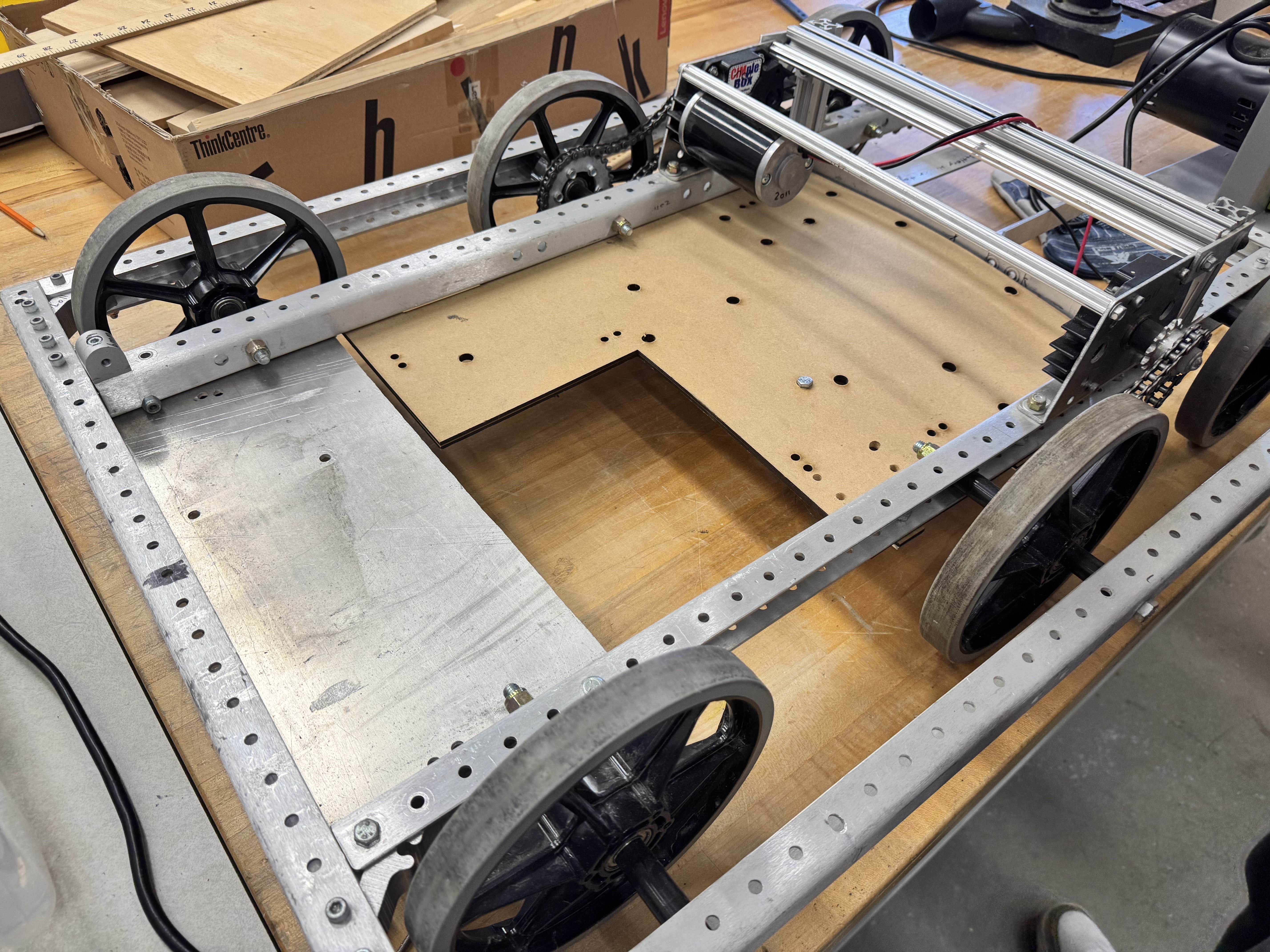 The drivebase of the old cannon
Finding these parts proved greatly beneficial to the development of the t-shirt cannon. However, the old cannon provded to be a safety hazard so I decided against using the cannon attachment, but the drivebase made a great starting point.
Air pressure is perhaps one of the most dangerous things to be messing around with. Unlike incompressible fluids, it can and will compress with relative ease. However, if you spend 5 minutes compressing air to a certain pressure, all it takes is one fault for all that energy to release in a small fraction of a second. This is extremely dangerous and nothing to play around with. The old t-shirt cannon used a makeshift pressure vessel made out of a PVC tube to hold about 100 psi. This is exactly what you should not do with pressure. PVC pipe is not rated for air pressure, it's rated for water pressure, where the liquid itself does not compress by any significant amount, so pressure largely equates to velocity of the water. Putting compressed air in such a pipe will eventually lead to rapid stress-cracks, which could possibly become a plastic fragment grenade. For this reason, it is best to always use factory-rated metal pressure vessels to store this much pressure, makeshift pressure vessels are nothing to play around with!
On the other hand, despite being over a decade old, the drivebase seemed great. A little bit of oil on the chains and it was rotating like it was brand new. All I had to do was install a missing motor (that happend to be right next to it), and it was good to go. Well, at least mechanically.
The motors used by this drivebase are CIMs (pictured below).
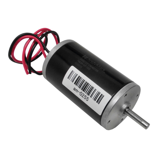 A CIM Motor, as sold by VEX Robotics in 2025
While the origins of this motor are largely debated (likely used to be used in wheelchairs), they are extremely cheap yet powerful, which makes them so commonplace in FRC (First Robotics Competition). As a matter of fact, the exact same SKU that was sold 15 years ago is still sold today. This luckily means I didn't need to search through any obscure documentation to find information about this motor.
However, one important thing I didn't have at the time was motor controllers. The CIM is a DC motor, which means that the output shaft RPM is proportional to the input voltage. However, no microcontroller can provide a variable voltage signal from 0-12V for the huge amount of current this motor draws. For this reason, external boards known as motor controllers exist. These external boards take in a PWM (Pulsed Width Modulation) signal from about any microcontroller, and convert it to the variable voltage that the CIM wants. These tend to be extremely expensive due to the large MOSFETs needed in the controller, but I'll cover how I dealt with that later.
Now that the drivebase had been largely dealt with, the task at hand was to design the actual cannon apparatus.
The Cannon
As I previously mentioned, the primary design motive with this section is safety. Many of the design choices were made soley for purposes of being safe and sane.
While designs using components like slingshots, trebuchets, and flywheels exist, they are far more mechanically complex than using compressed air, and generally lack the "wow" factor of something being launched insanely far out of a tube. Additionally, the added complexity they pose with a large number of moving parts was hard to deal with in the short timeline I had for myself.
Even with air, I was confused how I would both have a large volume of air for multiple shots, and also not use all the air in one shot. If I had a single tank hooked up to the barrel, it would empty all the air in one shot very quickly. Timing would be of little avail aswell, as valves with enough precision to do short bursts did not come cheap.
After some thinking, I devised what I called the two tank system (because it had two tanks, very creative of me). There would be one very large tank holding the bulk of the air, and this large tank would be used to fill up a smaller tank each shot. Then, the smaller tank would be used in its entirety to propel the t-shirt. This would allow many shots, without putting large strain on any valve, and would give me predictable launch characteristics by controlling the pressure in the secondary tank.
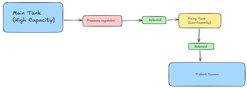 A diagram of how the air would flow with this design
With that out of the way, it was time to figure out the specific components in this design. For the solenoid values, any NPT (National Pipe Thread) electric solenoids would serve. There would be nothing special about it.
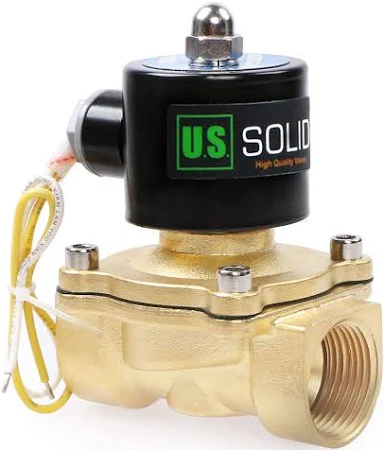 One of the solenoids I used, the other was identical except for being smaller
It was decided that the main firing mechanism would use a 2" PVC barrel attached to the solenoid and tank. This was sufficient size to make sure the t-shirt fit snug in the cannon and made a good seal.
Now it came time to figure out what to use for the tanks. The large tank was relatively simple to figure out. I found a decently priced 7 gallon large tank I wanted to use.
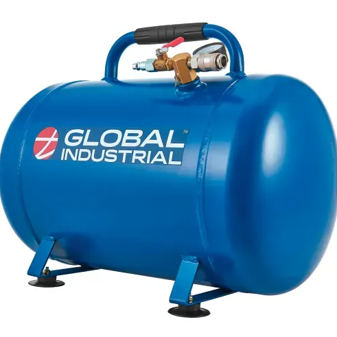 The large tank I used
However, finding a small tank was a pain. I searched so many places for a tank that was both small and had a large output diameter. Nobody had anything that could possibly match it. But then I found my solution, the humble fire extinguisher. This piece of equipment that should be found in every house has both a decently small volume, high pressure rating, and large output diameter. With how commonly found this piece of equipment is, I figured I could just order it and find a way to attach it later.
Everything in the cannon used the National Pipe Thread (NPT) standard. This standard is very common is all forms of piping hence is easy to work with. However, when I recieved the fire extinguisher, it has some sort of obscure threads I could not decipher. I had to go on a wild goose chase to figure out what I was even looking at.
(This is a relatively long section, click the arrow if you want to read it).
Making an adapter for the fire extinguisher
Side Quest: Making an Adapter for the Fire Extinguisher
This task did not prove to be easy by any means.
- I had no clue what I was looking at
- There were no published specifications online
- The Manufacturer refused to provide me information regarding the thread
I had spent nearly 20 hours in total just searching for any glimpse of info. Although I heard that fire equipment generally uses a UNF (Unified National Fine) thread, I had no other leads. Despite having no thread tester, I decided that maybe I could 3d print various threads to match. The outer diameter of the thread was roughly 1 inch, so I figured to try the 1-12 UNF standard which matched that.
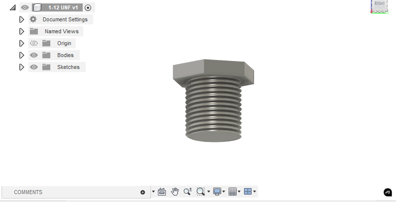 The thread tester I made in Fusion 360 for the UNF 1-12 thread
And much to my surprise disapointment, it worked. The reason to be unhappy here is that adapters for this thread are about as rare as things get. They are either nonexistant or from obscure websites that offer to custom-machine it. Clearly another solution had to be found to get this extinguisher working.
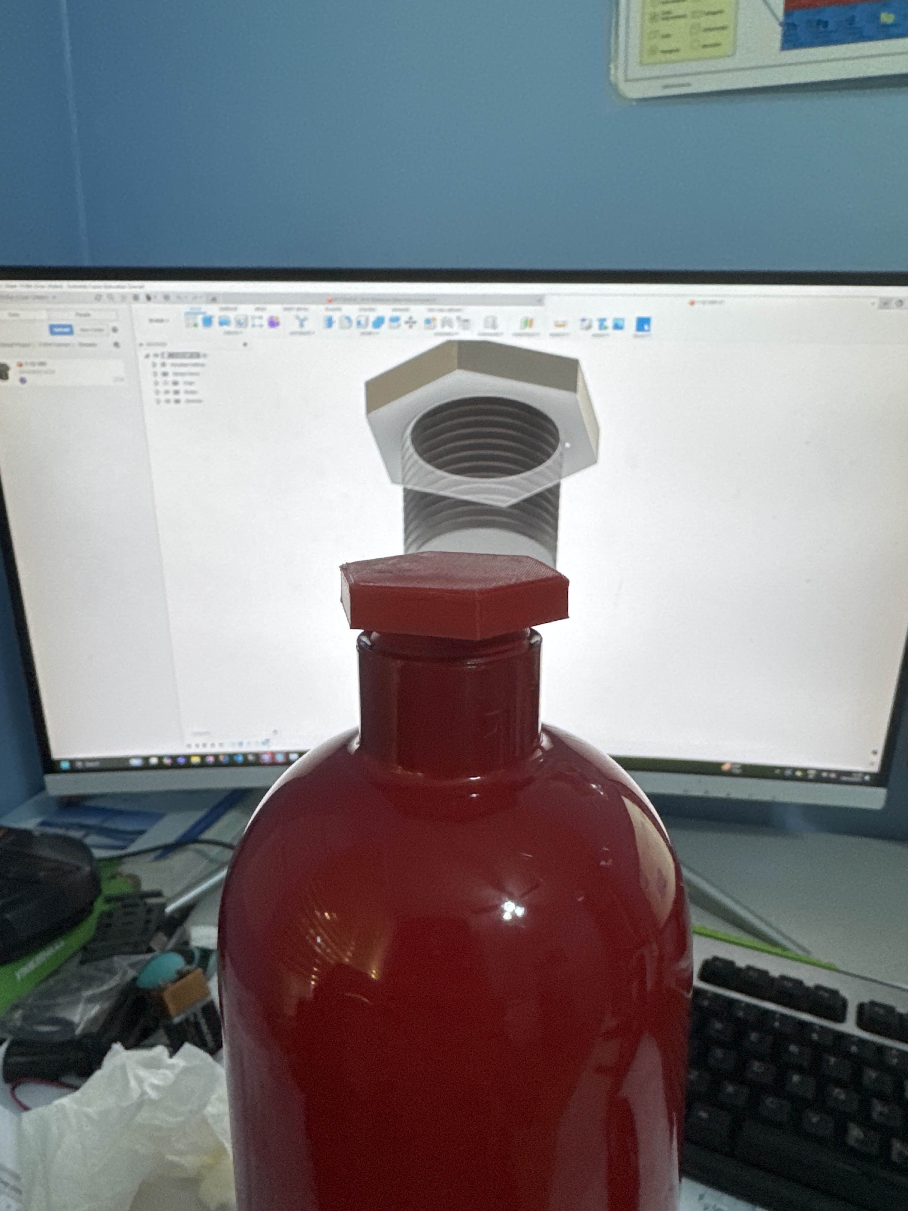 The thread tester I made, mounted on the extinguisher
From this point, I decided to go down the rabbit hole of 3d printing. At the time, I just got my hands on a shiny new spool of GF (Glass Fibre) infused Nylon filament from Polymaker. This filament demonstrated remarkable strength and it seemed like a good idea to design an adapter with it.
So I went to work in Fusion 360, and I made an adapter to convert this thread to 1-inch NPT.
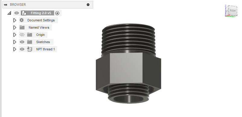 UNF 1-12 to NPT 1" adapter
I figured that running this adapter without at least a simulation to test it would be a bad idea, so I also ran a stress-test simulation and it did pass with flying colors.
 Literally "passed with flying colors"
However, once I actually printed it, things turned south very quick in terms of actual functionality. While this may look nice, it actually broke in the fire exintinguisher. This was due to unexpected stresses that came from the cooling during 3D printing, which made the material extremely brittle. It became clear that 3D printing was not a good option, and I had to find an alternative.
 I managed to snap the thing into two
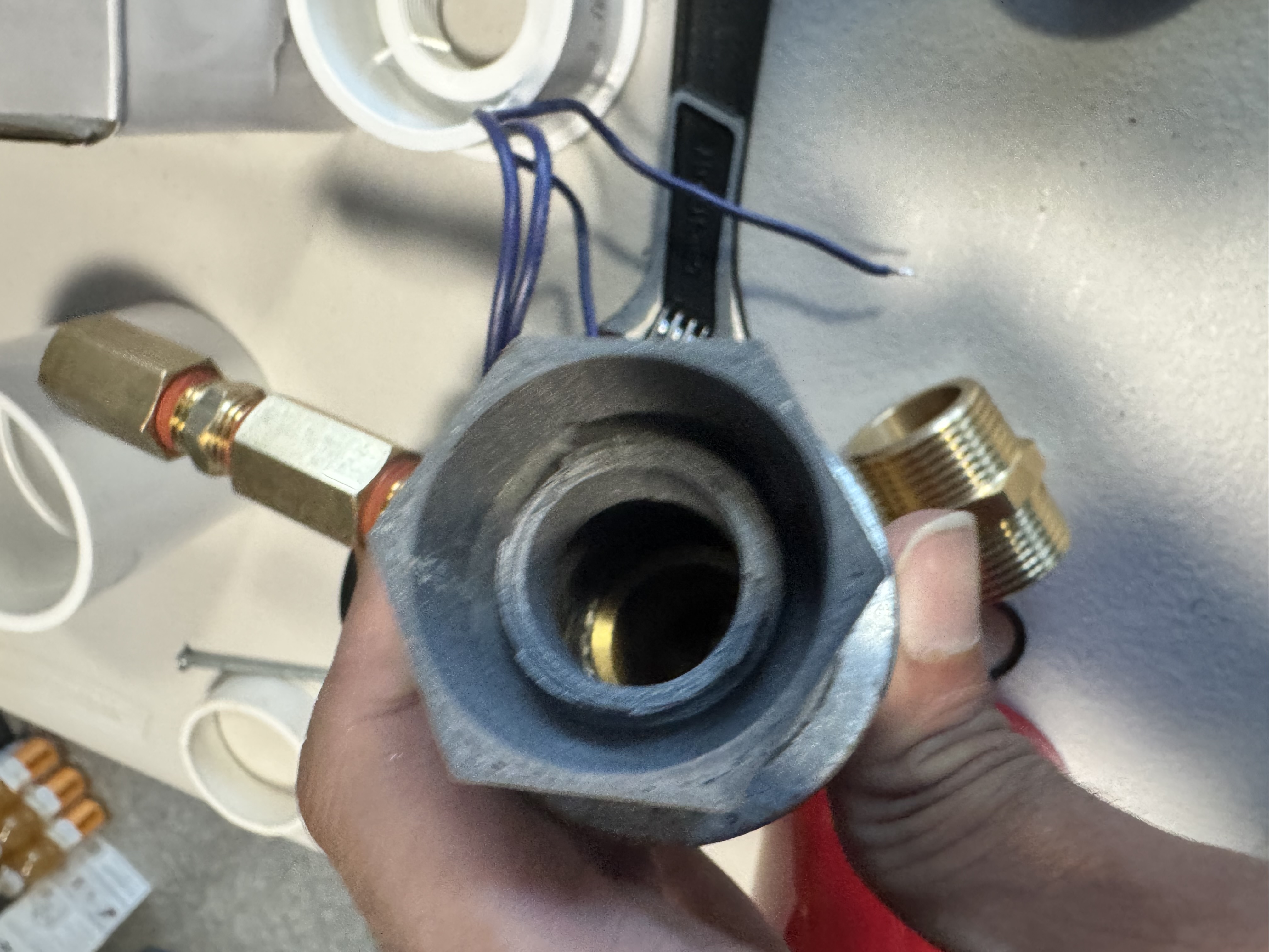
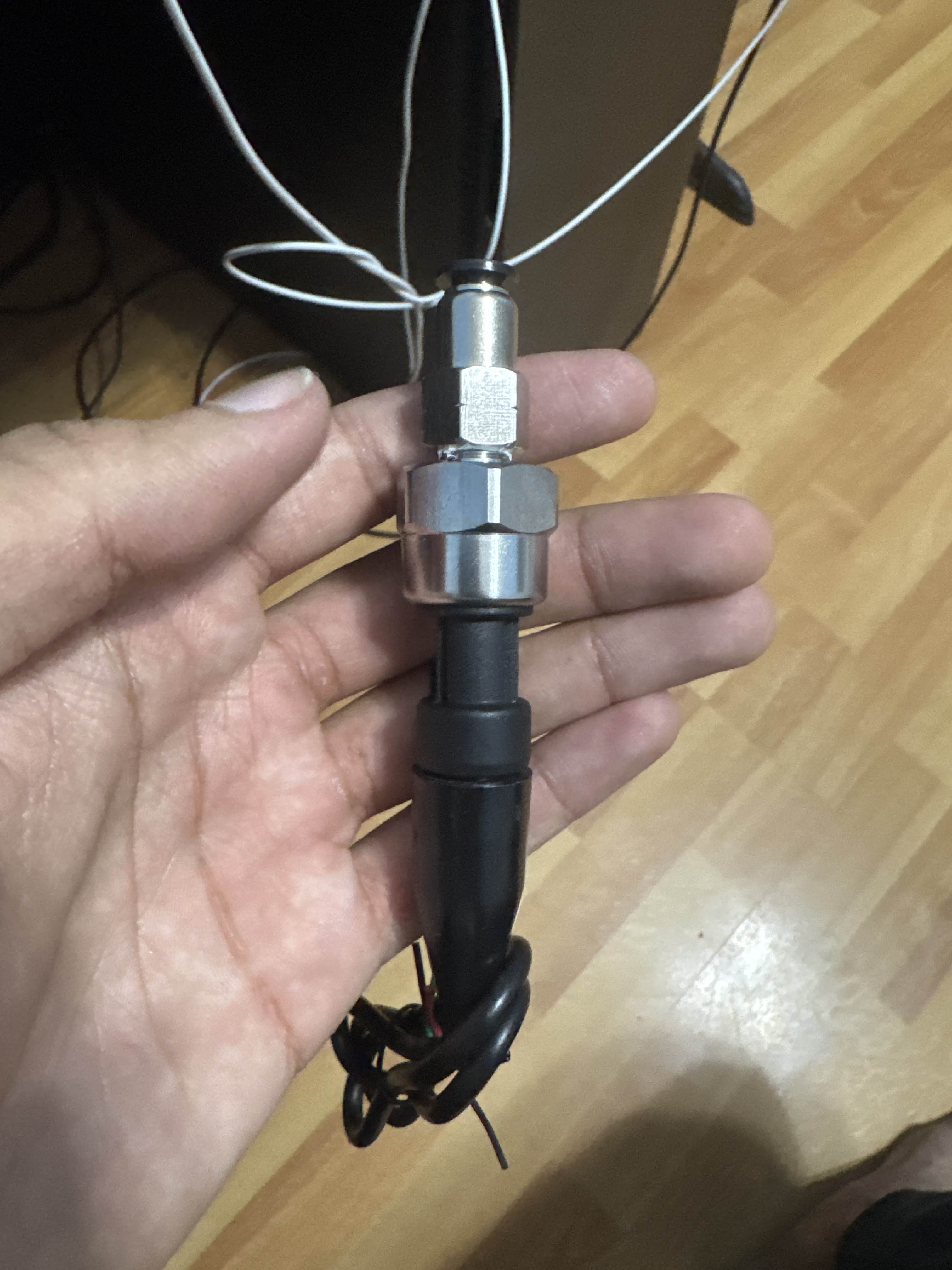
With all of this in mind, I decided that it was best to JB-Weld in a metal adapter, and that did the trick just great. With some calculations done, this should be able to sustain the load.
Now that i'm done talking about mechanical design, its time to get into the electricals.
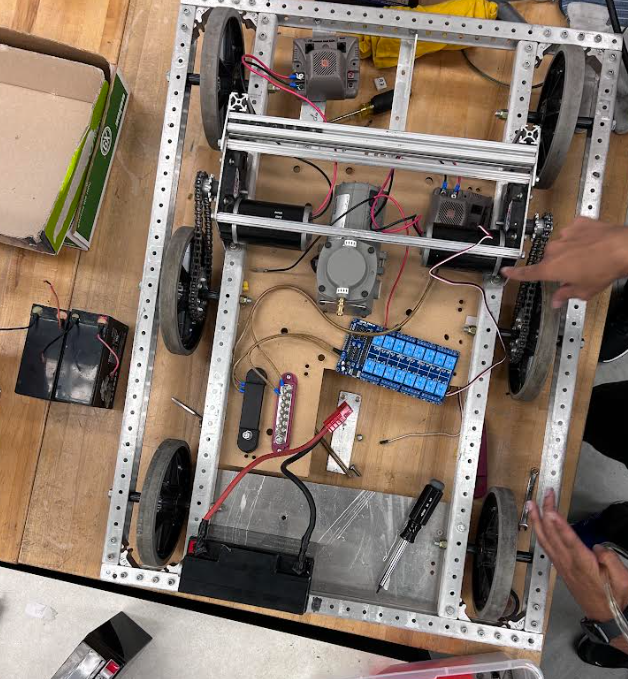
Here is the full design of the robot:
Electrical Design
The goal of the electrical system is to provide power to the solenoids, the drivetrain, and take input from pressure sensors.
Part 1: The Design
I decided to use a SainSmart 12-relay board to provide enough relays to power the whole system, and a Raspberry Pi as the main computer as I had a few on hand. This also allowed me to easily use a Xbox controller as the means of controlling of the cannon.
Here is a wiring diagram demonstrating how all the componenbts connect. I decided to use a 18Ah 12V battery that is similar to the one used in the First Robotics Competition. This is tried and tested and gives me the desired voltage. Beyond this, I also decided to wire everything up with busbars, these bus bars allows for easy connections, as long as safety is taken to avoid bridging the rails.
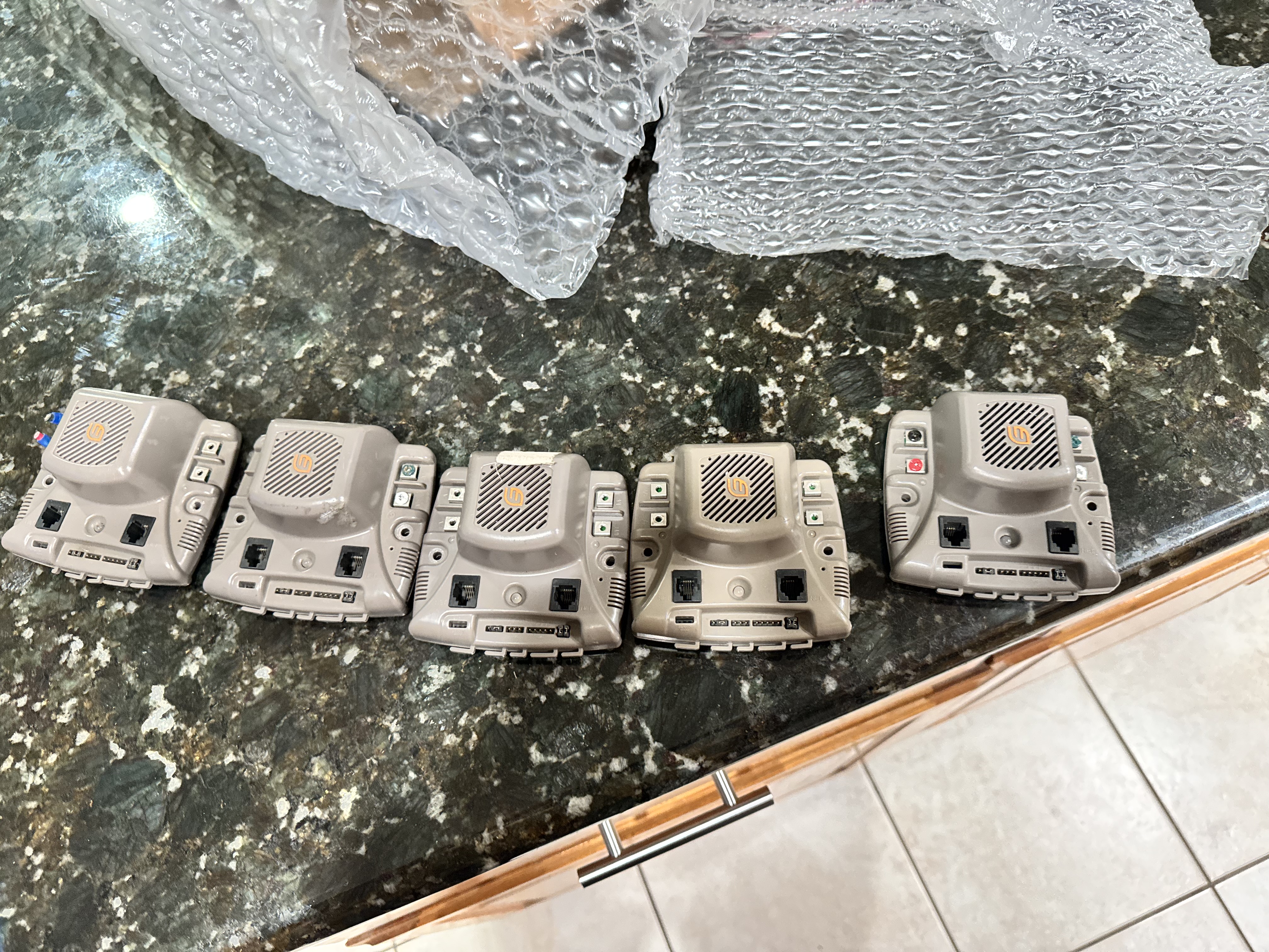
To control the and the pump, I chose to use TI Jaguar Controllers. These old motor controllers come really cheap on ebay, and I found a lot of 5 for circa 30 dollars.
I also made the choice to use engine pressure transducers as pressure sensors, these work extremely well and have high precision while being budget-friendly.
The Build
Now came time to build the cannon. The electricals proved to be the most daunting part of the whole process, but lets start off simple with the cannon build.
Part 1: The Cannon
Building the cannon was largely just attaching PVC pipes and tubes to the specification. Once this was done, I tested it with the help of some friends as it would be hard to test it alone.
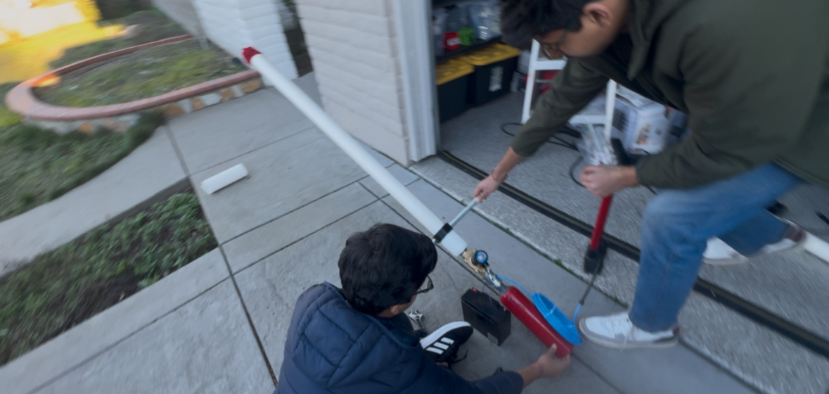
The cannon worked great and somehow landed a t-shirt on my roof that I still haven't been able to get down. With this confidence from the cannon working, it became time to wire it all up.
Part 2: Wiring
Once all the components arrived, the first job was laying out all the non-microcontroller electricals. This is due to the fact that the microcontroller wiring would be tightly integrated with the software, which was not done yet.
As a first order of business, the relay board and jaguars were mounted.
From here, it was time to connect up the actual cannon and the MCU wires. This was relatively simple and some sample code proved to me that the wiring worked fine. This was quite encouraging as I was nearing the deadline and significant progress was seen.
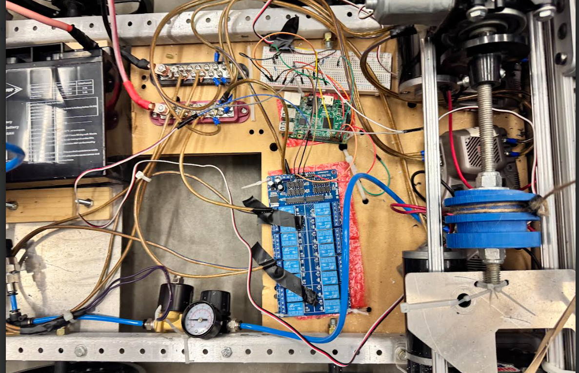
There was intentional choice made to do the whole thing on breadboards instead of a more permanent solution to allow for rapid prototyping and changes to the system.
With this, the electricals were completed and all that was left to do was mount the actual cannon.
Part 3: Mechanical
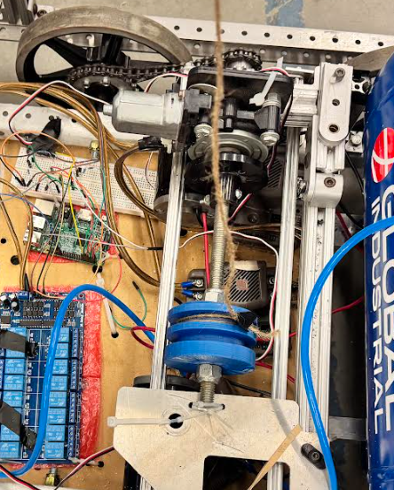
The mechanical part of this whole project proved to be the simplest part as all I had to design was a post to hold the cannon on. I used some aluminum brackets and extrusion to complete the mount as shown. The cannon was held with a threaded rod as the axle.
This worked very well, so the only thing left mechanically was the winch. I wanted to add a winch to allo wthe cannon to assume various angles (it is actually shown in the photo above). All it needed was an old FRC "window slider" motor and some twine. This was a relatively quick addition but worked wonderfully. The 3d printed spool was actually a cut up piece of an old robot intake.
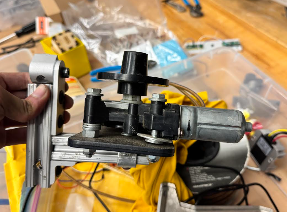 The slider motor and the constructed winch
With this implemented, the only thing left was to program the whole thing and then demo.
Part 4: The Software
In terms of software, the decision to use the Raspberry Pi made things a lot easier. I used a bluetooth driver for the Xbox controller known as XPadNeo, which gave me a very easy means of reading the controller input. The TI Jaguar motor controllers were easily controlled by the PWM pins of the Raspberry PIs. The pressure sensors required an extra ADC (Analog to Digital Converter) chip that did not arrive in time, so the demo ran with the sensors off and using manual regulators to set safety margins.
The source code can be found at https://github.com/XboxBedrock/t-shirt-cannon/blob/main/main.py, although there is some system setup on the PI that had to be done that is not yet documented. With this out of the way, the only thing left was the demo itself.
The Demo
It came time for the demo. I decided to use an external air compressor at the start of the demo instead of using the onboard compressor. This was to keep volume at a managable level. I found out in the gym, the echo was so high that the internal compressor made a terribly loud noise.
It became time for the first demo, and the cannon worked beautifully. So much so that I had to turn the power down before the first event.
The next day, the event ran great, and everyone was amazed by the cannon. I guess high schoolers like t-shirts being launched at absurd speeds.
Conclusion
Overall, I consider this project a success. While some of the telemetry and logging I wanted did not make the cut for the demo, the project is modular enough that I can still add it back for the next demo. I think the next steps for this project is to increase the fire rate and make it autonomously operable. I've always been interested in using OpenCV for target detection. The next goal appears to be the school homecoming parade, so i'll have to make changes to fit the scenario.